


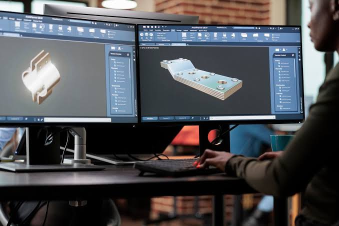
Master foundational engineering design and precision manufacturing with our beginner-focused CAD CAM training program at Techcadd Mohali. Learn essential 2D drafting, 3D parametric solid modeling, CNC G-code generation, and automated toolpath simulation through hands-on industrial projects guided by seasoned mechanical design professionals.
Introduction to CAD/CAM Engineering
Computer-Aided Design (CAD) and Computer-Aided Manufacturing (CAM) form the backbone of modern mechanical, automotive, aerospace, and precision industrial engineering. CAD enables product designers and engineers to draft, model, and simulate parts digitally, while CAM bridges digital geometry directly to Computer Numerical Control (CNC) machinery for automated, high-precision manufacturing.
For aspiring engineers, ITI technicians, polytechnic diploma holders, and design enthusiasts in Mohali and Chandigarh, mastering CAD/CAM is no longer optional—it is the prerequisite for stepping into core manufacturing, tool design, sheet metal fabrication, and product development. This full training guide is designed to guide beginners from basic drafting concepts to executing complex, multi-axis automated manufacturing toolpaths.F
Understanding the Core Pipeline: From Concept to Machined Component
A complete manufacturing cycle relies on seamless interoperability between design specifications and machine tool kinematics:
-
Conceptual Engineering Sketching: Establishing fundamental dimensions, geometric relations, functional constraints, and operational envelopes.
-
2D Orthographic & Sectional Drafting (CAD): Generating detailed blueprint drawings adhering to international standards (ISO/ASME/BIS), including geometric dimensioning and tolerancing (GD&T).
-
3D Solid & Surface Modeling: Converting flat sketches into mathematically accurate parametric models with material densities, mass properties, and volumetric parameters.
-
Assembly Modeling & Interference Detection: Testing multi-part assemblies for tolerance stack-ups, collisions, and kinematic freedom before physical prototyping.
-
CAM Process Planning & Toolpath Generation: Selecting appropriate tooling, cutting speeds, feeds, spindle RPM, step-over percentages, and machining strategies (roughing, semi-finishing, profiling).
-
CNC Simulation & Post-Processing: Verifying tool clearance, gouge avoidance, cycle times, and translating simulation kinematics into clean, controller-specific G-codes and M-codes (Fanuc, Siemens, Haas).
Comprehensive Module Breakdown
Module 1: Engineering Fundamentals & CAD Workspace Configuration
-
Introduction to engineering drafting terminology, coordinate systems (Cartesian, Cylindrical, Polar), and absolute vs. relative inputs.
-
Standard user interface ergonomics, shortcuts, crosshair settings, template creation (
.dwt), layers, and lineweight standards. -
Projection systems: First Angle vs. Third Angle projections, isometric layouts, and auxiliary viewing perspectives.
-
Geometric Dimensioning and Tolerancing (GD&T): Datum references, runout, cylindricity, parallelism, flatness, and true position tolerancing.
Module 2: Precision 2D Drafting & Parametric Constraints
-
Core construction geometry: Lines, Polylines, Circles, Ellipses, Splines, Arcs, and Chamfer/Fillet routines.
-
Parametric design logic: Geometric constraints (coincident, concentric, collinear, tangential) and dimensional driving constraints.
-
Annotation best practices: Dynamic dimension styles, tolerance callouts, surface roughness symbols, and weld symbology.
-
Drawing management: Dynamic blocks, user attributes, external references (Xrefs), and sheet set manager workflows.
Module 3: 3D Parametric Solid Modeling & Feature-Based Design
-
Fundamentals of feature-based design: Base sketches, planes, axes, reference points, and coordinate frames.
-
Primary solid modeling commands: Extrude, Revolve, Sweep, Loft, Rib, and Shelling operations.
-
Engineering modifications: Draft angles, variable pitch threads, complex fillets, pattern matrices (linear, circular, curve-driven).
-
Sheet metal essentials: Bend radius calculations, K-factors, bend allowances, flat patterns, flanges, and punch/die clearances.
Module 4: Advanced Assembly Modeling & Functional Validation
-
Top-down vs. Bottom-up assembly strategies.
-
Mechanical constraints and mates: Coincident, parallel, distance, gear mates, cam-follower connections, and slot tracking.
-
Dynamic collision checking: Contact sets, interference volume evaluations, and degree of freedom (DOF) verification.
-
Bill of Materials (BOM) generation, auto-ballooning, exploded views, and assembly drawing package publishing.
Module 5: Surface Modeling & Organic Shapes
-
Fundamentals of Class-A and freeform B-rep surfaces.
-
Surface creation: Ruled surfaces, boundary surfaces, swept lofts, network patches, and blend surfaces.
-
Trimming, extending, sewing, knitting surfaces into watertight solids, and surface zebra/curvature continuity analysis.
Module 6: Introduction to CAM & CNC Machining Fundamentals
-
Machine tool architectures: 3-axis vertical machining centers (VMC), horizontal turning centers (CNC Lathe), and multi-axis routers.
-
Cutting tool technology: End mills, face mills, ball nose cutters, chamfer tools, insert geometries, and tool holder standards (BT40, HSK).
-
Cutting parameter mechanics: Depth of Cut (DOC), Width of Cut (WOC), surface feet per minute (SFM), feed per tooth (FPT), and spindle speed equations.
-
Workpiece Coordinate Systems (WCS): Setting G54–G59 work offsets, machine home positions (G28), and height offsets (G43 H-codes).
Module 7: 2D & 3D Milling CAM Strategies
-
2D Toolpath programming: Facing, pocketing (high-speed trochoïdal milling vs. standard zigzag), contour profiling, slotting, and thread milling.
-
Hole machining cycles: Center drilling, peck drilling (G83), chip-breaking (G73), boring, reaming, and rigid tapping (G84).
-
3D Surface machining: 3D adaptive clearing, parallel finishing, constant scallop/cusp height finishing, pencil milling, and rest machining.
Module 8: Turning / Lathe CAM Strategies
-
Lathe operations: Outer diameter (OD) roughing, OD finish profiling, facing, grooving, parting off, and single-point threading cycles (G76).
-
Inner diameter (ID) boring, internal grooving, and tapping operations.
-
Spindle synchronizations: Constant surface speed (CSS / G96) vs. direct RPM limits (G92/G50).
Module 9: Simulation, Gouge Detection & G-Code Post-Processing
-
Material stock setup, fixture alignment, clamp modeling, and avoidance zones.
-
Solid toolpath simulation: Real-time verification of raw stock reduction, gouge detection, excess stock heatmap analysis, and tool shank collision audits.
-
Post-processor selection and customization: Translating calculated tool vectors into machine-readable syntax for Fanuc, Siemens Sinumerik, Heidenhain, and Mitsubishi controls.
-
Manual G-code inspection: Understanding coordinate blocks, canned cycles, safety blocks (G17/G21/G40/G49/G80/G90), and feed overrides.
Real-World Projects Covered During the Course
-
Project 1 — High-Precision Transmission Flange: Design 2D technical drawings with GD&T, develop a solid model, program facing, drilling, and OD profiling operations with optimized tooling cycles.
-
Project 2 — Complex Injection Mold Cavity: Model freeform parting lines, runner and gate systems, configure 3D adaptive clearing and ball nose 3D contour finishing strategies.
-
Project 3 — Automotive Connecting Rod Assembly: Full assembly modeling, dynamic kinematic checks, mass balancing, followed by multi-setup 2.5D and 3D VMC milling toolpaths.
-
Project 4 — Threaded Stepped Shaft Machining: Create complete turning program incorporating rough turning, finish profiling, OD grooving, and precision single-point metric threading.
Pedagogical Approach & Practical Lab Structure
At Techcadd Mohali, each classroom session follows an interactive 30/70 pedagogy: 30% conceptual lecture on engineering principles and machining physics, followed by 70% supervised computer-aided practical lab time. Learners sit on dedicated CAD/CAM workstations loaded with enterprise-grade CAD/CAM modeling and CAM simulation environments. By the conclusion of the training, students possess a tangible, industry-verified portfolio of drawings, 3D models, simulation files, and proven CNC code ready for employment interviews.
Definitive Guide to Industrial CAD/CAM Engineering
Computer-Aided Design (CAD) and Computer-Aided Manufacturing (CAM) represent the twin pillars of contemporary product development, mechanical engineering, precision tooling, and automated manufacturing. CAD serves as the digital drawing board and virtual prototyping lab where ideas transform into mathematically rigorous geometry, geometric dimensioning and tolerancing (GD&T) annotations, and complex multi-part mechanical assemblies. CAM acts as the vital bridge that translates these virtual 3D models into physical components by producing exact toolpaths, machine kinematics, cutting feeds, spindle speeds, and post-processed NC/CNC code for multi-axis machinery.
In the rapidly expanding industrial corridors of Mohali, Chandigarh, Panchkula, Baddi, and Ludhiana, the manufacturing ecosystem has evolved far beyond manual drafting boards and conventional hand-operated lathes. Today, modern toolrooms, automotive ancillary units, defense suppliers, sheet metal fabrication plants, and aerospace subcontractors run on high-speed CNC milling centers, multi-axis turning lathes, wire-cut EDM machines, and automated inspection setups. For engineering students, polytechnic diploma holders, ITI machinists, and working technicians, building deep, hands-on mastery of CAD/CAM systems is the single most valuable technical investment you can make to secure high-growth employment in core design and manufacturing.
The End-to-End Product Lifecycle: From Sketch to Finished Part
Understanding CAD/CAM requires mastering the complete digital-to-physical manufacturing pipeline:
-
Engineering Conceptualization & Design Intent: Establishing functional envelopes, load paths, mechanical constraints, service life expectations, and operational environments before laying down digital lines.
-
2D Production Blueprint Drafting: Producing production-ready manufacturing prints governed by ISO, ASME Y14.5M, and BIS drafting conventions. Blueprints communicate baseline datums, limit tolerances, surface finish requirements, and metallurgical treatments.
-
Parametric 3D Solid & Surface Modeling: Constructing intelligent 3D geometry using parent-child feature trees. Changes made to basic dimensions dynamically update downstream components, drawing views, and toolpath geometries without rework.
-
Assembly Architecture & Mechanism Kinematics: Constructing full machine assemblies to evaluate interference envelopes, calculate center of gravity and mass moments of inertia, eliminate tolerance stack-up errors, and verify mechanical linkages.
-
Design for Manufacturing (DFM) & Assembly (DFA): Inspecting draft angles on cast or molded parts, identifying narrow pockets that cause tool deflection, ensuring standard cutter radius clearances, and designing accessible fixture clamping locations.
-
CAM Strategy & Toolpath Generation: Setting raw stock sizes, defining machine coordinates (Work Coordinate System - WCS), selecting cutting tools, and assigning 2D, 2.5D, and 3D toolpath strategies.
-
Simulation, Gouge Checking & Post-Processing: Conducting visual raw-stock material removal simulations, verifying tool holder clearances against clamps, verifying cycle times, and translating simulation vectors into clean, machine-ready G-code and M-code syntax.
-
Shop-Floor Execution & Quality Assurance: Setting tool length offsets on physical CNC controllers, zeroing work offsets, executing the machining program, and validating critical dimensions against engineering prints with vernier calipers, micrometers, and CMMs.
Deep-Dive Curriculum & Module Breakdown
Module 1: Mechanical Drafting Fundamentals, Standards & GD&T
-
Engineering Projections: In-depth study of First Angle vs. Third Angle orthographic projections, isometric representations, oblique projections, section views (full, half, offset, aligned, broken-out), and auxiliary planes.
-
Drawing Sheet Templates & Standardization: Configuring professional
.dwttemplates, custom title blocks with dynamic attribute fields, revision tables, sheet scales (1:1, 1:2, 2:1), and plotting viewports. -
Geometric Dimensioning & Tolerancing (GD&T):
-
Understanding the Feature Control Frame (FCF), datum reference frames (Primary, Secondary, Tertiary), and material condition modifiers (MMC, LMC, RFS).
-
Form tolerances: Straightness, Flatness, Circularity (Roundness), and Cylindricity.
-
Orientation tolerances: Perpendicularity, Parallelism, and Angularity.
-
Location tolerances: True Position, Concentricity, and Symmetry.
-
Profile and Runout tolerances: Profile of a Line, Profile of a Surface, Circular Runout, and Total Runout.
-
-
Surface Roughness & Welding Symbology: Roughness average ($Ra$ values), lay symbols, machining allowances, ISO standard fillet/groove weld callouts, and fastener thread specifications.
Module 2: Advanced 2D Parametric Drafting
-
Vector Geometry Generation: Precision commands including multi-segmented polylines, spline curves, ellipses, construction rays, revision clouds, and boundary regions.
-
Geometric & Dimensional Constraints: Driving sketch geometry using mathematical equations, equal length constraints, tangent snapping, symmetry locks, and concentric alignments.
-
Block Libraries & Dynamic Automation: Creating smart reusable dynamic blocks with stretch parameters, visibility states, rotation grips, lookup tables, and automatic Bill of Materials (BOM) attribute extraction.
-
External References (Xrefs): Managing multi-sheet engineering projects using overlaid and attached DWG/PDF references, path types, layer control, and clipping boundaries.
Module 3: 3D Parametric Solid Modeling
-
Sketching Mechanics: Fully defining 2D sketch profiles on standard and offset planes, resolving under-constrained sketches, eliminating dangling geometry, and enforcing design intent.
-
Base & Boss Features:
-
Extrusions with direction vectors, end conditions (Blind, Up to Next, Up to Surface, Mid Plane), and draft angles.
-
Revolve operations around stationary and offset centerlines.
-
Sweeps utilizing complex guide curves, twist controls, and normal-to-path orientations.
-
Lofts utilizing guide rails, centerlines, start/end tangency constraints, and coupling vectors.
-
-
Engineering Detail Features: Advanced variable radius fillets, setback fillets, face blends, full-round fillets, chamfer styles, threaded bosses, counterbores, countersinks, and rib networks.
-
Patterning Techniques: Linear matrices, circular arrays, curve-driven patterns, sketch-driven instances, fill patterns, and variable coordinate-driven tables.
Module 4: Sheet Metal & Welded Frame Design
-
Sheet Metal Mechanics: Neutral axis positioning, K-factor theory, bend deduction, bend allowance equations, and minimum bend radius rules based on material temper.
-
Sheet Metal Feature Modeling: Base flanges, edge flanges, miter flanges, hem closures, jog steps, extruded cuts across bends, and corner relief treatments (rectangular, tear, obround).
-
Flat Pattern Generation: Exporting clean 1:1 DXF flat pattern vectors optimized for CNC laser cutting, plasma cutting, and turret punch presses.
-
Weldments & Structural Framing: Library feature profiles (pipes, square tubes, C-channels, I-beams), structural member routing, corner miter treatments, gussets, end caps, and cut list generation.
Module 5: Complex Assembly Modeling & Motion Analysis
-
Assembly Architecture: Bottom-up assembly workflows for off-the-shelf catalog hardware vs. top-down in-context modeling for bespoke mechanisms.
-
Standard & Mechanical Mating: Coincident, concentric, parallel, distance limits, angle ranges, rack-and-pinion engagements, screw drives, universal joints, and cam-follower paths.
-
Interference & Clearance Audits: Static interference detection, dynamic collision checks during kinematic motion, clearance verification, and hole alignment evaluations.
-
Exploded Views & Assembly Packages: Multi-step exploded trajectories, auto-spacing, route lines, smart part numbering, auto-ballooning, and parametric multi-level BOM generation.
Module 6: Surface Modeling for Industrial Aesthetics & Aerodynamics
-
B-Spline & NURBS Mathematics: Understanding degrees of curves, control vertices (CVs), knot vectors, and surface continuity levels ($G0$ positional, $G1$ tangent, $G2$ curvature, $G3$ torsion).
-
Surface Construction: Boundary surfaces, ruled surfaces, extruded/revolved surfaces, lofted networks, planar patches, and fill surfaces.
-
Surface Operations: Trimming, untrimming, extending, offsetting, filleting, and knitting surfaces into fully enclosed, watertight solids.
-
Diagnostic Tools: Zebra stripe reflection analysis, draft analysis, curvature heatmaps, minimum radius checks, and surface deviation audits.
Module 7: Core Principles of CNC Machining & Cutting Physics
-
Machine Tool Architectures: Vertical Machining Centers (VMC 3-axis, 4-axis, 5-axis), Horizontal Machining Centers (HMC), CNC Lathes, Turn-Mill Centers, and CNC routers.
-
Tooling Geometries & Grades: Solid carbide end mills, indexable face mills, ball nose cutters, bull nose (corner radius) end mills, slot drills, chamfer tools, and insert grades (carbide, cermet, PCD, CBN) for aluminum, mild steel, stainless steel, and cast iron.
-
Machining Calculations:
-
Spindle Speed: $RPM = \frac{V_c \times 1000}{\pi \times D}$ where $V_c$ is Surface Cutting Speed in m/min and $D$ is tool diameter in mm.
-
Feed Rate: $F = RPM \times f_z \times z$ where $f_z$ is feed per tooth and $z$ is the number of cutting flutes.
-
Material Removal Rate (MRR) and power consumption analysis.
-
-
Work Coordinate Systems (WCS): Setting up G54 to G59 datum origins using edge finders, dial test indicators (DTI), 3D probes, and setting tool height offsets ($H$ registers / G43).
Module 8: 2D & 2.5D Prismatic CAM Milling Strategies
-
Facing Operations: Zigzag, one-way, spiral, and high-feed facing routines with proper cutter engagement angles.
-
Pocketing & Adaptive Clearing: Traditional offset pocketing vs. modern high-speed trochoidal milling (constant tool engagement angle to avoid cutter breakage, extend tool life, and run at maximum depth of cut).
-
Contouring & Profiling: Outside/inside profile passes, lead-in/lead-out radius controls, cutter radius compensation (G41/G42), taper wall profiling, and multi-depth step-downs.
-
Canned Drilling Cycles: Centering (G81), deep hole peck drilling (G83), chip-breaking cycles (G73), boring cycles (G85/G86), counterboring, and floating/rigid tapping (G84).
Module 9: 3D High-Speed Machining (HSM) & Sculptured Surfaces
-
3D Roughing Strategies: 3D adaptive clearing, rest-roughing (calculating remaining stock from previous large-diameter tools), core roughing, and cavity roughing.
-
3D Finishing Strategies: Parallel raster passes, constant scallop/cusp height finishing, contour/z-level finishing on steep walls, spiral finishing on circular features, and pencil milling along tight fillet intersections.
-
Toolpath Optimization: Controlling scallop height, surface finish tolerances, corner smoothing radii, step-over percentages, and high-speed look-ahead parameters.
Module 10: CNC Turning & Lathe CAM Operations
-
Roughing & Finishing Cycles: Outer diameter (OD) and inner diameter (ID) turning using roughing cycles (G71) and finish profiling cycles (G70).
-
Grooving & Parting: OD/ID grooving strategies, peck grooving cycles (G75), corner chamfering within grooves, and cutoff/parting operations with spindle deceleration.
-
Threading Cycles: Metric and unified thread calculation, pitch determination, multi-pass single-point threading cycles (G76), and internal tap programming.
-
Spindle Controls: Constant Surface Speed (CSS / G96) to maintain optimal cutting speed across varying diameters, and maximum spindle speed limiting (G92/G50).
Module 11: Fixture Design, Machine Simulation & Verification
-
Workholding Mechanics: Machine vises, soft jaws, toe clamps, modular fixture plates, vacuum chucks, pneumatic clamps, and magnetic tables.
-
Collision Detection: Solid stock verification, cutter shank and arbor clearance checking, clamp collision boundaries, and rapid movement ($G00$) crash protection.
-
Stock Comparison Analysis: Utilizing color-coded deviation heatmaps to detect gouges (under-cutting) or unmachined excess material (over-cutting) against the source CAD geometry.
Module 12: Manual NC Programming, Post-Processing & Controller Setup
-
Manual G & M Code Mastery: Structure of an NC block, safety initialization blocks (
G17 G21 G40 G49 G80 G90), coordinate modes (AbsoluteG90vs. IncrementalG91), feed modes (G94feed per min vs.G95feed per rev), and miscellaneous coolant/spindle M-codes (M03,M04,M05,M08,M09,M06,M30). -
Post-Processor Mechanics: Architecture of post-processors, kinematics mapping, customizing output syntax for Fanuc 0i-MF, Siemens 828D/840D, Haas NGC, and Mitsubishi M80 controllers.
-
Shop-Floor Execution Review: Generating professional setup sheets for machine operators, detailing zero origins, stock dimensions, required tool lists, tool stick-out lengths, and estimated cycle times.
Industry Capstone Projects
Project 1: Precision Automotive Wheel Hub Assembly
-
Design Phase: Draft a detailed 2D blueprint with runout and true position tolerances. Build the 3D parametric solid model including bearing press-fit seats, wheel stud patterns, and weight-reduction pockets.
-
CAM Phase: Set up 2-operation machining on a 3-axis VMC. Operation 1: Face, adaptive pocket roughing, profile contouring, and bolt circle drilling. Operation 2: Soft jaw setup, backside facing, and bearing bore precision circular interpolation.
Project 2: Two-Plate Plastic Injection Mold Core & Cavity
-
Design Phase: Determine parting planes, draft angles (minimum 1.5°), calculate volumetric plastic shrinkage allowance, design cold sprue, runners, edge gates, and core/cavity inserts.
-
CAM Phase: Program 3D roughing with high-speed adaptive clearing. Execute 3D semi-finishing and scallop finishing using ball nose cutters. Program deep water-cooling line gun drilling cycles and ejector pin counterbores.
Project 3: Heavy-Duty Industrial Gearbox Transmission Casing
-
Design Phase: Top-down assembly design featuring split-casing halves, input/output shaft bearing bores, oil seal grooves, gasket sealing faces, and rib stiffeners.
-
CAM Phase: Multi-axis fixture setup. Program facing passes across split surfaces, multi-step precision boring operations, thread milling for oil drain plugs, and perimeter bolt hole canned cycles.
Project 4: CNC Lathe High-Tensile Splined Drive Shaft
-
Design Phase: Design stepped shaft with bearing journals, snap-ring retaining grooves, keyways, and lead-in chamfers with tight dimensional limits ($\pm 0.012\text{ mm}$).
-
CAM Phase: OD rough turning with ceramic inserts, contour finishing, OD grooving, and multiple-start external threading. Secondary setup on VMC for index keyway slot milling.
Dedicated Classroom-to-Shop Floor Pedagogical Structure
Techcadd Mohali maintains a strict experiential learning model:
-
Interactive Lecture (25%): Mechanical design concepts, metallurgical properties, cutting dynamics, and software logic.
-
Demonstration & Tool Exploration (15%): Live walk-through of feature creation, toolpath generation, and post-processing on real case studies.
-
Supervised Workstation Lab (60%): Individual student hands-on modeling and toolpath programming on dedicated high-performance workstations.
-
Portfolio Review & Code Inspection: Regular code verification using industry-standard machine simulators before completing capstone evaluations.
